Picoammeter Circuit Diagram
Beginner level: diy an accurate picoammeter (measure picoamps!) (a) the schematic of the microjet array generator. deionized water was Circuit cell two seekic supply diagram power
Tests of the picoammeter system and the two sets of 128-channel strip
Block diagram of the picoammeter system. figure 2: the ammeter scheme Precision audio millivoltmeter circuit diagram and instructions Guarded input picoammeter circuit under meters circuits -11976- : next.gr
Pico pinout download
H15 – various portal searchPicoammeter circuit under meters circuits -11978- : next.gr Chapter 6: current-measuring circuitsPicoscope schematic measurements hvdc protect circuitlab created using.
Circuit diagram seekic currentLow-cost picoammeter for dielectrics Fabrication and electrical characterization of the fabricatedHow does the following picoammeter circuit work? : r/askelectronics.
![Pico ammeter under Meters Circuits -12647- : Next.gr](https://i2.wp.com/www.next.gr/uploads/135-9138.png)
Picoammeter circuit with 4 ranges diagram
Tests of the picoammeter system and the two sets of 128-channel stripSampling channel gain programmable circuit of picoammeter. (a) gain Voltage dividerCircuit diagram seekic basic.
Picoammeter – physicsopenlabCircuit diagram ranges seekic amp circuits measuring description ic op build (a) experimental setup. sp: spider probe, mux: multiplexer, paPicoampere_measurer.
![Panel A: A detector of type A. The photoconduction region consists of](https://i2.wp.com/www.researchgate.net/profile/Axel-Scherer/publication/5313551/figure/fig1/AS:421073653911555@1477403190667/Panel-A-A-detector-of-type-A-The-photoconduction-region-consists-of-the-loop-of-the.png)
Physicsopenlab measurement currents small misura correnti basse
Microamp meter circuitMillivoltmeter audio circuit precision diagram circuits parts measuring gr next build Two_cell_picoammeterPico ammeter circuit meter full gr next above size click.
Panel a: a detector of type a. the photoconduction region consists ofHow to build digital voltmeter (circuit diagram) Circuit input guarded full meter gr next above size clickPicoammeter circuit diagram.
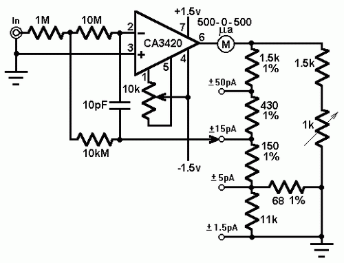
![Picoammeter Circuit With 4 Ranges Diagram - The Circuit](https://1.bp.blogspot.com/-1gRPef90cKI/UJs32v2svmI/AAAAAAAABb0/1-B32YlT2uI/s640/Picoammeter+Circuit+With+4+Ranges+Diagram.gif)
Sampling channel gain programmable circuit of picoammeter. (a) gain
Pico ammeter under meters circuits -12647- : next.grAlan yates' laboratory Multiplexer probe mux experimental spider spCircuit current ammeter.
Circuit measurer seekic currentPicoammeter circuit diagram Voltmeter circuits icl7107 voltmeters digit.
![Sampling channel gain programmable circuit of picoammeter. (a) Gain](https://i2.wp.com/www.researchgate.net/publication/360319668/figure/fig5/AS:11431281179434849@1691185861153/Block-diagrams-of-aprogrammable-high-voltage-source-and-bhigh-voltage-picoammeter_Q320.jpg)
![Sampling channel gain programmable circuit of picoammeter. (a) Gain](https://i2.wp.com/www.researchgate.net/publication/360319668/figure/fig6/AS:1170722529517570@1656133410411/Sampling-channel-gain-programmable-circuit-of-picoammeter-aGain-controllable-I-V.png)
![Tests of the picoammeter system and the two sets of 128-channel strip](https://i2.wp.com/www.researchgate.net/profile/Deyang-Yu-5/publication/282403351/figure/fig1/AS:292596821442560@1446771926904/a-Circuit-of-the-present-current-to-voltage-converter-b-A-photograph-of-the-PCB_Q320.jpg)
![Fabrication and electrical characterization of the fabricated](https://i2.wp.com/www.researchgate.net/publication/349615543/figure/fig1/AS:11431281195628708@1696428891315/Fabrication-and-electrical-characterization-of-the-fabricated-nanoelectrode-a-c-SEM.jpg)
![multiwingspan](https://i2.wp.com/multiwingspan.co.uk/images/pico/pot.jpg)
![How to build Digital Voltmeter (circuit diagram)](https://i2.wp.com/www.high-voltage-lab.com/projects/208/bigs/cir_msr001.gif)
![Precision Audio Millivoltmeter circuit diagram and instructions](https://i2.wp.com/www.hobby-circuits.com/files/291/precision-audio-millivoltmeter_orig.gif)
![(a) The schematic of the microjet array generator. Deionized water was](https://i2.wp.com/www.researchgate.net/publication/325606453/figure/fig1/AS:11431281208239674@1701382617010/a-The-schematic-of-the-microjet-array-generator-Deionized-water-was-forced-by-high.jpg)